Here’s another platform solution we developed for our client FK Group, who were working for Main Contractor Sir Robert McAlpine. They needed a solution to deal with the load spread requirements of the MEWP during their finishing works. We proposed utilising ALIMATS®. The working area was located on the newly constructed hard landscaping, adjacent to the façade of two elevations.
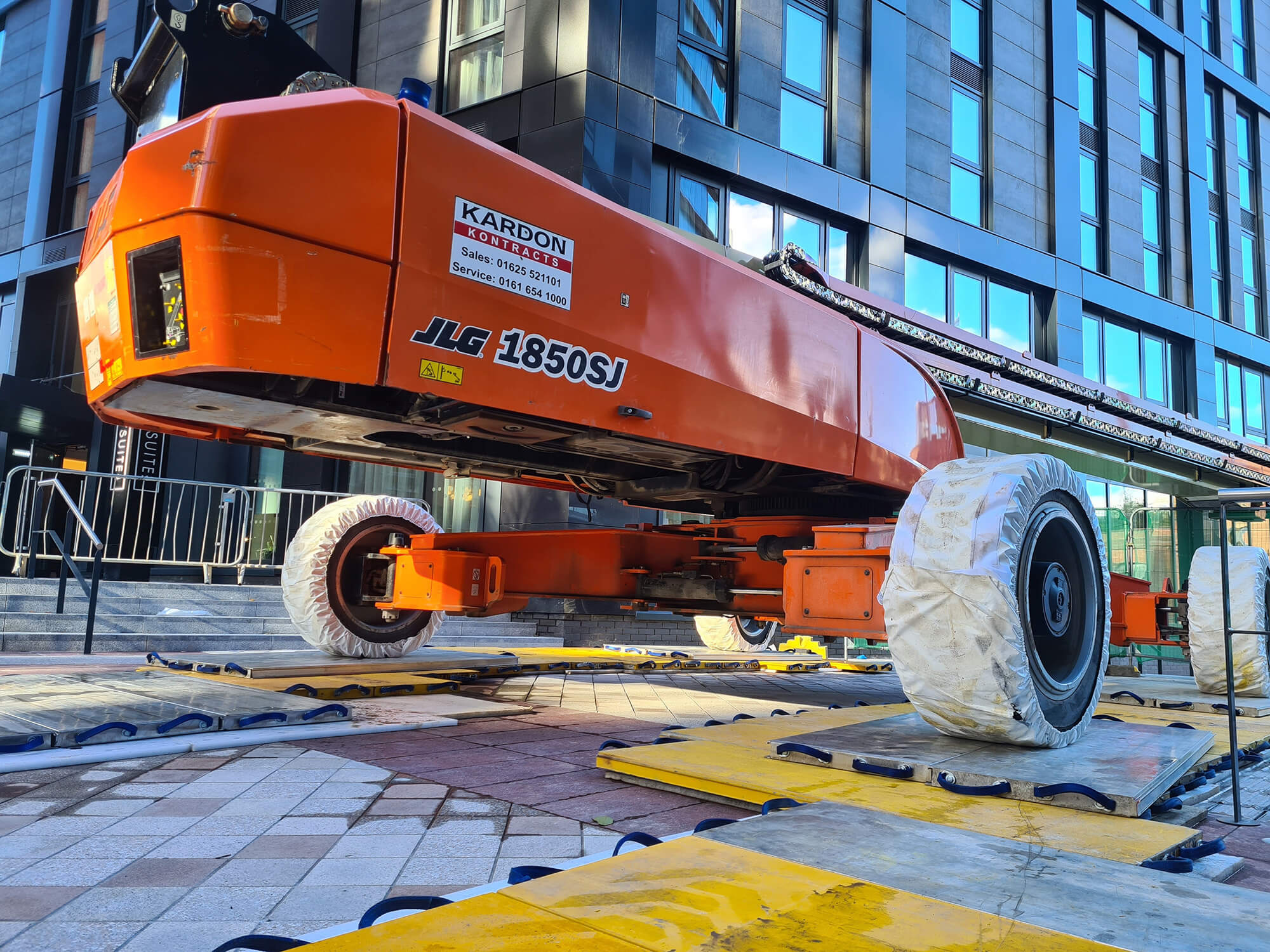
The machine selected was a JLG 1850SJ Ultra Series Telescopic Boom Lift. It weighs 27.4 tonnes, has a maximum platform height of 56.57m (185 ft 7 in) and horizontal reach of 24.38m (80 ft). Something we had to overcome was the extendable/retractile axles. During transport, the machine width is 2.49m (8ft 2 in) and when the axles are extended, the machine width is 5.03m (16 ft 6 in).
To ensure the axles can be extended within the footprint of the load spread area, a frictionless layer of two plastic mats were placed above our ALIMATS® modules, which is something we’ve done before, where a similar size machine was used.
With all MEWP’S there are two load cases that need considering – Tracking and Operating. The latter imposing loads similar to mobile crane outriggers, but via the wheels. Both conditions were considered in our proposal, and this is what was approved for use. When the machine arrived on site, it was tracked between two immovable bollards (Load Case 1 – Tracking), then onto the platform with the plastic layers where the axles were extended/retracted (Load Case 2).
The machine was then tracked to its final position (Load Case 3 – Tracking/Operating) where an additional layer of mats was used, which simulates our standard outrigger mat arrangement.
This is better explained on our drawings GA01, GA02 and GA04 inclusive. Ethafoam was also adopted below the ALIMATS® modules to ensure they could work as intended (distribute the load) and protect the newly laid hardstanding. To make sure the system was set up exactly in accordance with our drawings, we provided the supply and installation too. We also visited site once the project was complete, on a Saturday, to strip down and remove.